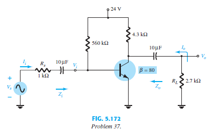
Question: For the network of Fig. 5.172: /
For the network of Fig. 5.172:
> Walter and Nancy provide 60% of the support of their daughter (age 18) and son-in-law (age 22). The son-in-law (John) is a full-time student at a local university, and the daughter (Stella) holds various part-time jobs from which she earns $11,000. Walte
> Taylor, age 18, is claimed as a dependent by her parents. For 2021, she has the following income: $6,000 wages from a summer job, $800 interest from a money market account, and $300 interest from City of Chicago bonds. a. What is Taylor’s taxable income
> Wesley and Camilla (ages 90 and 88, respectively) live in an assisted care facility and for 2020 and 2021 received their support from the following sources: Percentage of Support Social Security benefits………………………………………….16% Son………………………………………………
> During 2021, Jenny, age 14, lives in a household with her father, uncle, and grandmother. The household is maintained by the uncle. The parties, all of whom file separate returns, have AGI as follows: father ($30,000), uncle ($50,000), and grandmother ($
> Trip Garage, Inc. (459 Ellis Avenue, Harrisburg, PA 17111), is an accrual basis taxpayer that repairs automobiles. In late December 2021, the company repaired Samuel Mosley’s car and charged him $1,000. Samuel did not think the problem had been fixed and
> Determine the gross income of the beneficiaries in the following cases: a. Justin’s employer was downsizing and offered employees an amount equal to one year’s salary if the employee would voluntarily retire. b. Trina contracted a disease and was unable
> In November 2021, Kortney (who is a self-employed management consultant) travels from Chicago to Barcelona (Spain) on business. She is gone 10 days (including 2 days of travel) during which time she spends 5 days conducting business and 3 days sightseein
> For tax year 2021, determine the number of dependents in each of the following independent situations: a. Ben and Molly (ages 48 and 46, respectively) are married and furnish more than 50% of the support of their two children, Libby (age 18) and Sam (age
> Al is a medical doctor who conducts his practice as a sole proprietor. During 2021, he received cash of $280,000 for medical services. Of the amount collected, $40,000 was for services provided in 2020. At the end of 2021, Al had accounts receivable of $
> Determine the amount of the standard deduction allowed for 2021 in the following independent situations. In each case, assume that the taxpayer is claimed as another person’s dependent. a. Curtis, age 18, has income as follows: $700 interest from a certi
> Compute the taxable income for 2021 for Aiden on the basis of the following information. Aiden is married but has not seen or heard from his wife since 2019. Salary………………………………………………………………………………………………….$ 80,000 Interest on bonds issued by City of Boston…
> Tristan, who is single, operates three sole proprietorships that generate the following information in 2021 (none are “specified services” businesses). Tristan chooses not to aggregate the businesses. She also earns $1
> Ben and Molly are married and will file jointly. Ben generates $300,000 of qualified business income from his single-member LLC (a law firm). He reports his business as a sole proprietorship. Wages paid by the law firm amount to $40,000; the law firm has
> Scott and Laura are married and will file a joint tax return. Scott has a sole proprietorship (not a “specified services” business) that generates qualified business income of $300,000. The proprietorship pays W–2 wages of $40,000 and holds property with
> Donald (a married taxpayer filing jointly) owns a wide variety of commercial rental properties held in a single-member LLC. Donald’s LLC reports rental income of $1,500,000. The LLC pays no W–2 wages; rather, it pays a management fee to an S corporation
> Ashley (a single taxpayer) is the owner of ABC LLC. The LLC (which reports as a sole proprietorship) generates QBI of $900,000 and is not a “specified services” business. ABC paid total W–2 wages of $300,000, and the total unadjusted basis of property he
> Peter owns and manages his single-member LLC that provides a wide variety of financial services to his clients. He is married and will file a joint tax return with his spouse, Marta. His LLC reports $300,000 of qualified business income, W–2 wages of $12
> Tyler, a self-employed taxpayer, travels from Denver to Miami primarily on business. He spends five days conducting business and two days sightseeing. His expenses are $400 (airfare), $150 per day (meals at local restaurants), and $300 per night (lodging
> Shelly has $200,000 of QBI from her local jewelry store (a sole proprietorship). Shelly’s proprietorship paid $30,000 in W–2 wages and has $20,000 of qualified property. Shelly’s spouse earned $75,100 of wages as an employee, they earned $20,000 of inter
> Melanie is employed full-time as an accountant for a national hardware chain. She recently started a private consulting practice, which provides tax advice and financial planning to the general public. For this purpose, she maintains an office in her hom
> During 2021, José, a self-employed technology consultant, made gifts in the following amounts: To Haley (José’s personal assistant) at Christmas …………………………………..$36 To Darryl (a key client)—$3 was for gift wrapping ……………………………………53 To Darryl’s wife (a hom
> Kim works for a clothing manufacturer as a dress designer. During 2021, she travels to New York City to attend five days of fashion shows and then spends three days sightseeing. Her expenses are as follows: Airfare ………………………………………………………………………$1,500 Lodgi
> In June 2021, Enrique and Denisse Espinosa traveled to Denver to attend a three-day conference sponsored by the American Society of Implant Dentistry. Denisse, a self-employed practicing oral surgeon, participated in scheduled technical sessions dealing
> On July 1, 2017, Brent purchases a new automobile for $40,000. He uses the car 80% for business and drives the car as follows: 8,000 miles in 2017, 19,000 miles in 2018, 20,000 miles in 2019, and 15,000 miles in 2020. Determine Brent’s basis in the busin
> Jackson, a self-employed taxpayer, uses his automobile 90% for business and during 2021 drove a total of 14,000 business miles. Information regarding his car expenses is listed below. Business parking ………………………………………………………………………$ 140 Auto insurance ……………
> Jamie purchased $100,000 of new office furniture for her business in June of the current year. Jamie understands that if she elects to use ADS to compute her regular income tax, there will be no difference between the cost recovery for computing the regu
> Dennis Harding is considering acquiring a new automobile that he will use 100% for business. The purchase price of the automobile would be $64,500. If Dennis leased the car for five years, the lease payments would be $875 per month. Dennis will acquire t
> On May 28, 2021, Mary purchased and placed in service a new $60,000 car. The car was used 60% for business, 20% for production of income, and 20% for personal use in 2021. In 2022, the usage changed to 40% for business, 30% for production of income, and
> Jayden calculates his 2021 income tax by using both the Tax Tables and the Tax Rate Schedules. Because the Tax Rate Schedules yield a slightly lower tax liability, he plans to pay this amount. a. Why is there a difference? b. Is Jayden’s approach permiss
> Classify each of the following expenditures paid in 2021 as a deduction for AGI, a deduction from AGI, or not deductible: a. Barak contributes to his H.R. 10 plan (i.e., a retirement plan for a self-employed individual). b. Keith pays child support to hi
> What are the major differences between the collector characteristics of a BJT transistor and the drain characteristics of a JFET transistor? Compare the units of each axis and the controlling variable. How does IC react to increasing levels of IB versus
> a. Determine VDS for VGS = 0 V and ID = 6 mA using the characteristics of Fig. 6.11. b. Using the results of part (a), calculate the resistance of the JFET for the region ID = 0 to 6 mA for VGS = 0 V. c. Determine VDS for VGS = - 1 V and ID = 3 mA. d. Us
> Given k = 0.4 * 10-3 A>V2 and ID(on) = 3 mA with VGS(on) = 4 V, determine VT.
> Using an average value of 2.9 mA for the IDSS of the 2N3797 MOSFET of Fig. 6.31, determine the level of VGS that will result in a maximum drain current of 20 mA if VP = - 5 V.
> Given ID = 4 mA at VGS = - 2 V, determine IDSS if VP = - 5 V.
> Given ID = 14 mA and VGS = 1 V, determine VP if IDSS = 9.5 mA for a depletion-type MOSFET.
> Sketch the transfer and drain characteristics of an n-channel depletion-type MOSFET with IDSS = 12 mA and VP = - 8 V for a range of VGS = - VP to VGS = 1 V.
> Given a depletion-type MOSFET with IDSS = 6 mA and VP = - 3 V, determine the drain cur- rent at VGS = - 1, 0, 1, and 2 V. Compare the difference in current levels between - 1 V and 0 V with the difference between 1 V and 2 V. In the positive VGS region,
> A resistor RC = 470 Ω is added to the network of Fig. 5.181 along with a bypass capacitor CE = 5 mF across the emitter resistor. If bD = 4000, VBET = 1.6 V and ro1 = ro2 = 40 kΩ for a packaged Darlington amplifier: a. Find the dc levels of VB1, VE2, and
> For the common-gate configuration of Fig. 8.92: a. Determine AvNL, Zi, and Zo. b. Sketch the two-port model of Fig. 5.75 with the parameters determined in part (a) in place. c. Determine AvL and Avs. d. Change RL to 2.2 kΩ and calcula
> The input impedance to a common-emitter transistor amplifier is 1.2 kΩ with b = 140, ro = 50 kΩ, and RL = 2.7 kΩ. Determine: a. re. b. Ib if VI = 30 mV. c. Ic. d. Ai = Io>Ii = IL>Ib. e. Av = VO>VI.
> For the source-follower network of Fig. 8.91: a. Determine AvNL, Zi, and Zo. b. Sketch the two-port model of Fig. 5.75 with the parameters determined in part (a) in place. c. Determine AvL and Avs. d. Change RL to 4.7 kΩ and calculate
> For the self-bias JFET network of Fig. 8.90: a. Determine AvNL, Zi, and Zo. b. Sketch the two-port model of Fig. 5.75 with the parameters determined in part (a) in place. c. Determine AvL and Avs. d. Change Rsig to 10 kΩ and calculate
> a. Describe in your own words the operation of the network of Fig. 6.45 with Vi = 0 V. b. If the “on” MOSFET of Fig. 6.45 (with Vi = 0 V) has a drain current of 4 mA with VDS = 0.1 V, what is the approximate resistance level of the device? If ID = 0.5 mA
> For the common-base network of Fig. 5.176:
> For the network of Fig. 5.175:
> For the emitter-stabilized network of Fig. 5.174:
> Repeat Problem 6 using the universal JFET bias curve
> For the voltage-divider configuration of Fig. 5.173:
> For the network of Fig. 5.171:
> Using the model of Fig. 5.16, determine the following for a common-emitter amplifier if b = 80, IE (dc) = 2 mA, and ro = 40 kΩ. a. Zi. b. Ib. c. Ai = Io>Ii = IL>IB if RL = 1.2 kΩ. d. Av if RL = 1.2 kΩ.
> a. What is the significant difference between the construction of an enhancement-type MOSFET and a depletion-type MOSFET? b. Sketch a p-channel enhancement-type MOSFET with the proper biasing applied (VDS 7 0 V, VGS 7 VT) and indicate the channel, the di
> For the fixed-bias configuration of Fig. 5.170: a. Determine AvNL, Zi, and Zo. b. Sketch the two-port model of Fig. 5.63 with the parameters determined in part (a) in place. c. Calculate the gain AvL = VO>VI. d. Determine the current gain AiL = Io>
> Repeat the analysis of problem 15 for the network of Fig. 9.83 with the addition of a source
> Repeat the analysis of problem 15 for the network of Fig. 9.82 with the addition of a source
> Repeat the analysis of problem 15 for the network of Fig. 9.81 with the addition of a source
> Repeat the analysis of problem 15 for the network of Fig. 9.80 with the addition of a source
> Repeat Problem 15 for the common-base configuration of Fig. 9.83. Keep in mind that the common-base configuration is a noninverting network when you consider the Miller effect.
> Repeat Problem 15 for the emitter-follower network of Fig. 9.82.
> Repeat Problem 15 for the emitter-stabilized network of Fig. 9.81.
> a. Compare the levels of stability for the fixed-bias configuration of Problem 65. b. Compare the levels of stability for the voltage-divider configuration of Problem 67. c. Which factors of parts (a) and (b) seem to have the most influence on the stabil
> For the common-base configuration of Fig. 5.18, an ac signal of 10 mV is applied, resulting in an ac emitter current of 0.5 mA. If a = 0.980, determine: a. Zi. b. Vo if RL = 1.2 kΩ. c. Av = VO>VI. d. Zo with ro = ∞ Ω. e. Ai = Io>Ii. f. Ib.
> Compare the relative values of stability for Problems 65 through 68. The results for Exercises 65 and 67 can be found in Appendix E. Can any general conclusions be derived from the results?
> For the network of Fig. 4.140, determine: a. S(ICO). b. S(VBE). c. S(), using T1 as the temperature at which the parameter values are specified and (T2) as 25% more than (T1). d. Determine the net change in IC if a change in operating conditions resul
> For the network of Fig. 4.125, determine: a. S(ICO). b. S(VBE). c. S(), using T1 as the temperature at which the parameter values are specified and (T2) as 25% more than (T1). d. Determine the net change in IC if a change in operating conditions resul
> For the network of Fig. 4.122, determine: a. S (ICO). b. S (VBE). c. S (), using T1 as the temperature at which the parameter values are specified and (T2) as 25% more than (T1). d. Determine the net change in IC if a change in operating conditions re
> Determine the following for the network of Fig. 4.118: a. S(ICO). b. S(VBE). c. S(), using T1 as the temperature at which the parameter values are specified and (T2) as 25% more than (T1). d. Determine the net change in IC if a change in operating con
> Answer the following questions about the circuit of Fig. 4.159: a. What happens to the voltage VC if the resistor RB is open? b. What should happen to VCE if  increases due to temperature? c. How will VE be affected when replacing the c
> Answer the following questions about the circuit of Fig. 4.158: a. What happens to the voltage VC if the transistor is replaced by one having a larger value of ? b. What happens to the voltage VCE if the ground leg of resistor RB2 opens (does not connec
> For the circuit of Fig. 4.157: a. Does VC increase or decrease if RB is increased? b. Does IC increase or decrease if is reduced? c. What happens to the saturation current if is increased? d. Does the collector current increase or decrease if VCC is
> The measurements appearing in Fig. 4.156 reveal that the networks are not operating properly. Be specific in describing why the levels obtained reflect a problem with the expected network behavior. In other words, the levels obtained reflect a very speci
> The measurements of Fig. 4.155 all reveal that the network is not functioning correctly. List as many reasons as you can for the measurements obtained.
> a. Given an Early voltage of VA = 100 V, determine ro if VCEQ = 8 V and ICQ = 4 mA. b. Using the results of part (a), find the change in IC for a change in VCE of 6 V at the same Q-point as part (a).
> a. Using the characteristics of Fig. 3.23e, determine ton and toff at a current of 2 mA. Note the use of log scales and the possible need to refer to Section 9.2. b. Repeat part (a) at a current of 10 mA. How have ton and toff changed with increase in co
> Design the transistor inverter of Fig. 4.154 to operate with a saturation current of 8 mA using a transistor with a beta of 100. Use a level of IB equal to 120% of IBmax and standard resistor values.
> Using the characteristics of Fig. 4.121, determine the appearance of the output waveform for the network of Fig. 4.153. Include the effects of VCEsat, and determine IB, IBmax, and ICsat when Vi = 10 V. Determine the collector-to-emitter resistance at sat
> Determine IE and VC for the network of Fig. 4.152.
> Determine VC and IB for the network of Fig. 4.151.
> Determine VC, VCE, and IC for the network of Fig. 4.150.
> Calculate the current I in the circuit of Fig. 4.149.
> For the circuit of Fig. 4.148, calculate the current I.
> a. Determine IC and VCE for the network of Fig. 4.118. b. Change  to 180 and determine the new value of IC and VCE for the network of Fig. 4.118. c. Determine the magnitude of the percentage change in IC and VCE using the following equa
> Calculate the current through the 2.2-kΩ load in the circuit of Fig. 4.147.
> In what ways is the construction of a depletion-type MOSFET similar to that of a JFET? In what ways is it different?
> a. Calculate the resistance associated with the JFET of Fig. 6.22 for VGS = V from ID = 0 mA to 4 mA. b. Repeat part (a) for VGS = - 0.5 V from ID = to 3 mA. c. Assigning the label ro to the result of part (a) and rd to that of part (b), use Eq. (6.1
> Using IDSS = 9 mA and VP = - 3 V for the characteristics of Fig. 6.22, calculate ID at VGS =—1 V using Shockley’s equation and compare to the level in Fig. 6.22.
> Determine VP for the characteristics of Fig. 6.22 using IDSS and ID at some value of VGS. That is, simply substitute into Shockley’s equation and solve for VP. Compare the result to the assumed value of - 3 V from the characteristics.
> Referring to Fig. 6.22, is the locus of pinch-off values defined by the region of VDS 6 VP = 3 V?
> Using the characteristics of Fig. 6.22, determine ID at VGS = - 0.7 V and VDS = 10 V.
> Define the region of operation for the JFET of Fig. 6.54 if
> For the 2N5457 JFET of Fig. 6.20, what is the power rating at a typical operating temperature of 45°C using the 5.0 mW/°C derating factor.
> Define the region of operation for the 2N5457 JFET of Fig. 6.20 using the range of IDSS and VP provided. That is, sketch the transfer curve defined by the maximum IDSS and VP and the transfer curve for the minimum IDSS and VP. Then, shade in the resultin
> A p-channel JFET has device parameters of IDSS = 7.5 mA and VP = 4 V. Sketch the transfer characteristics.
> Calculate collector currents for Q1 and Q2 in Fig. 4.146.
> Using the characteristics of Fig. 6.11: a. Determine the difference in drain current (for VDS 7 VP) between VGS = 0 V and VGS = -1 V. b. Repeat part (a) between VGS = -1 and -2 V. •312Repeat part (a) between VGS = -2 and -3 V. c. Repeat part (a) between
> Given the network of Fig. 5.190: a. Is the network properly biased? b. What problem in the network construction could cause VB to be 6.22 V and obtain the given waveform of Fig. 5.190?
> a. Based on a review of the characteristics of Fig. 5.126, which parameter changed the most with increase in temperature? b. Which changed the least? c. What are the maximum and minimum values of hfe? Is the change in magnitude significant? Was it expect
> a. Based on a review of the characteristics of Fig. 5.124, which parameter changed the least for the full range of collector current? b. Which parameter changed the most? c. What are the maximum and minimum values of 1>hoe? Is the approximation 1>hoe ǁ R
> a. If hre = 2 * 10-4 at IC = 1 mA on Fig. 5.124, determine the approximate value of hre at 0.1 mA. b. For the value of hre determined in part (a), can hre be ignored as a good approximation if Av = 210?
> a. If hoe = 20 mS at IC = 1 mA of Fig. 5.124, what is the approximate value of hoe at IC = 10 mA? b. Determine its resistive value at 10 mA and compare to a resistive load of 6.8 kΩ. Is it a good approximation to ignore the effects of 1>hoe in this case?

