Question: The infinite network of resistors shown in
The infinite network of resistors shown in Fig. P26.83 is known as an attenuator chain, since this chain of resistors causes the potential difference between the upper and lower wires to decrease, or attenuate, along the length of the chain.
Fig. P26.83:
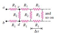
(a). Show that if the potential difference between the points a and b in Fig. 26.83 is Vab, then the potential difference between points c and d is Vcd = Vab/(1 +
Transcribed Image Text:
Rị c R1 R1 a and R23 R2{ R2 so on w R, d R R1 Ax
> One method for determining the amount of corn in early Native American diets is the stable isotope ratio analysis (SIRA) technique. As corn photosynthesizes, it concentrates the isotope carbon-13, whereas most other plants concentrate carbon-12. Overreli
> A 2.60-N metal bar, 0.850 m long and having a resistance of 10.0 Ω, rests horizontally on conducting wires connecting it to the circuit shown in Fig. P27.62. The bar is in a uniform, horizontal, 1.60-T magnetic field and is not attach
> A straight piece of conducting wire with mass M and length L is placed on a frictionless incline tilted at an angle
> In deriving the force on one of the long, current-carrying conductors in Section 28.4, why did we use the magnetic field due to only one of the conductors? That is, why didn’t we use the total magnetic field due to both conductors?
> A mass spectrograph is used to measure the masses of ions, or to separate ions of different masses (see Section 27.5). In one design for such an instrument, ions with mass m and charge q are accelerated through a potential difference V. They then enter a
> Suppose the electric field between the plates in Fig. 27.24 is 1.88 × 10⁴ V/m and the magnetic field in both regions is 0.682 T. If the source contains the three isotopes of krypton, 82Kr, 84Kr, and 86Kr, and the ions are singly charged, fin
> A particle with negative charge q and mass m = 2.58 × 10⁻¹⁵ kg is traveling through a region containing a uniform magnetic field
> You wish to hit a target from several meters away with a charged coin having a mass of 4.25 g and a charge of +2500 µC. The coin is given an initial velocity of 12.8 m/s, and a downward, uniform electric field with field strength 27.5 N/C exists througho
> In a shunt-wound dc motor with the field coils and rotor connected in parallel (Fig. E27.47), the resistance Rf of the field coils is 106 Ω, and the resistance Rr of the rotor is 5.9 Ω. When a potential difference of 120 V is applied to the brushes and t
> In the Bohr model of the hydrogen atom (see Section 39.3), in the lowest energy state the electron orbits the proton at a speed of 2.2 × 10⁶ m/s in a circular orbit of radius 5.3 × 10⁻¹¹ m. (a). What is the orbital period of the electron? (b). If the o
> If two deuterium nuclei (charge +e, mass 3.34 × 10⁻²⁷ kg) get close enough together, the attraction of the strong nuclear force will fuse them to make an isotope of helium, releasing vast amounts of energy. The range of this force is about 10-15 m. This
> A particle with charge 7.26 × 10⁻⁸ C is moving in a region where there is a uniform 0.650-T magnetic field in the +x-direction. At a particular instant, the velocity of the particle has components vx = -1.68 × 10⁴ m/s, vy = -3.11 × 10⁴ m/s, and vz = 5.85
> When a particle of charge q > 0 moves with a velocity of
> The electronics supply company where you work has two different resistors, R1and R2, in its inventory, and you must measure the values of their resistances. Unfortunately, stock is low, and all you have are R1 and R2 in parallel and in series—and you can
> You set up the circuit shown in Fig. 26.20, where C = 5.00 × 10⁻⁶ F. At time t = 0, you close the switch and then measure the charge q on the capacitor as a function of the current i in the resistor. Your results are given in the table: (a
> Suppose you have three long, parallel wires arranged so that in cross section they are at the corners of an equilateral triangle. Is there any way to arrange the currents so that all three wires attract each other? So that all three wires repel each othe
> You connect a number of identical light bulbs to a flashlight battery. (a). What happens to the brightness of each bulb as more and more bulbs are added to the circuit if you connect them (i) in series and (ii) in parallel? (b). Will the battery last l
> You set up the circuit shown in Fig. 26.22a, where R = 196 Ω. You close the switch at time t = 0 and measure the magnitude i of the current in the resistor R as a function of time t since the switch was closed. Your results are shown in Fig.
> A capacitor that is initially uncharged is connected in series with a resistor and an emf source with
> A dc motor with its rotor and field coils connected in series has an internal resistance of 3.2 Ω. When the motor is running at full load on a 120-V line, the emf in the rotor is 105 V. (a). What is the current drawn by the motor from the line? (b). Wh
> In the Bainbridge mass spectrometer (see Fig. 27.24), the magnetic-field magnitude in the velocity selector is 0.510 T, and ions having a speed of 1.82 × 10⁶ m/s pass through undeflected. Fig. 27.24: (a). What is the electric-field magnit
> A 224- Ω resistor and a 589- Ω resistor are connected in series across a 90.0-V line. (a). What is the voltage across each resistor? (b). A voltmeter connected across the 224- Ω resistor reads 23.8 V. Find the voltmeter resistance. (c). Find the readi
> A 2.36-µF capacitor that is initially uncharged is connected in series with a 5.86- Ω resistor and an emf source with
> (See Problem 26.67.) Problem 26.67: Figure P26.67 employs a convention often used in circuit diagrams. The battery (or other power supply) is not shown explicitly. It is understood that the point at the top, labeled “36.0 V,â
> The circuit shown in Fig. P26.74, called a Wheatstone bridge, is used to determine the value of an unknown resistor X by comparison with three resistors M, N, and P whose resistances can be varied. For each setting, the resistance of each resistor is pre
> Point an in Fig. P26.73 is maintained at a constant potential of 400 V above ground. (See Problem 26.67.) Fig. P26.73: (a). What is the reading of a voltmeter with the proper range and with resistance 5.00 × 10⁴Ω whe
> A 6.00-µF capacitor that is initially uncharged is connected in series with a 5.00- resistor and an emf source with
> A 2.00-µF capacitor that is initially uncharged is connected in series with a 6.00-k Ω resistor and an emf source with
> The capacitor in Fig. P26.70 is initially uncharged. The switch S is closed at t = 0. Fig. P26.70: (a). Immediately after the switch is closed, what is the current through each resistor? (b). What is the final charge on the capacitor? R1 = 8.00 N
> Two parallel conductors carrying current in the same direction attract each other. If they are permitted to move toward each other, the forces of attraction do work. From where does the energy come? Does this contradict the assertion in Chapter 27 that m
> A resistor R1 consumes electrical power P1 when connected to an emf
> The 20.0 cm × 35.0 cm rectangular circuit shown in Fig. E27.41 is hinged alongside ab. It carries a clockwise 5.00-A current and is located in a uniform 1.20-T magnetic field oriented perpendicular to two of its sides, as shown. Fig. E27.4
> Figure P26.67 employs a convention often used in circuit diagrams. The battery (or other power supply) is not shown explicitly. It is understood that the point at the top, labeled “36.0 V,” is connected to the positive
> In the circuit shown in Fig. P26.66 all the resistors are rated at a maximum power of 2.00 W. What is the maximum emf
> In the circuit shown in Fig. P26.65, the current in the 20.0-V battery is 5.00 A in the direction shown and the voltage across the 8.00- resistor is 16.0 V, with the lower end of the resistor at higher potential. Find Fig. P26.65: (a). the emf (inclu
> (a). Find the current through the battery and each resistor in the circuit shown in Fig. P26.62. Fig. P26.62: (b). What is the equivalent resistance of the resistor network? R = 1.00 R2 R = 1.00 0 ww | 14.0 3= 2,00 0 V R4 = 2.00 0 1.00 N
> Find the current through each of the three resistors of the circuit shown in Fig. P26.61. The emf sources have negligible internal resistance. Fig. P26.61: 20.0 V + 5.00 N ww $2.00 C4.00_+ Ω 36.0 V + 14.0 V
> What must the emf
> Calculate the three currents I1, I2, and I3 indicated in the circuit diagram shown in Fig. P26.59. Fig. P26.59: / /
> For the circuit shown in Fig. P26.58 a 20.0-Ω resistor is embedded in a large block of ice at 0.00°C, and the battery has negligible internal resistance. At what rate (in g/s) is this circuit melting the ice? (The latent he
> (a). Find the potential of point a with respect to point b in Fig. P26.57. (b). If points a and b are connected by a wire with negligible resistance, find the current in the 12.0-V battery. Fig. P26.57: 1.00 N 12.0 V b1.00 N 10.0 V wwtw 1.00 0 8.0
> A cylinder of iron is placed so that it is free to rotate around its axis. Initially the cylinder is at rest, and a magnetic field is applied to the cylinder so that it is magnetized in a direction parallel to its axis. If the direction of the external f
> The plane of a 5.0 cm × 8.0 cm rectangular loop of wire is parallel to a 0.19-T magnetic field. The loop carries a current of 6.2 A. (a). What torque acts on the loop? (b). What is the magnetic moment of the loop? (c). What is the maximum torque that
> Each of the three resistors in Fig. P26.56 has a resistance of 2.4Ω and can dissipate a maximum of 48 W without becoming excessively heated. What is the maximum power the circuit can dissipate? Fig. P26.56:
> The two identical light bulbs in Example 26.2 (Section 26.1) are connected in parallel to a different source, one with
> In Fig. P26.54, the battery has negligible internal resistance and
> Cell membranes across a wide variety of organisms have a capacitance per unit area of 1 µF/cm2. For the electrical signal in a nerve to propagate down the axon, the charge on the membrane “capacitor” must change. What time constant is required when the i
> In a simple model of an axon conducting a nerve signal, ions move across the cell membrane through open ion channels, which act as purely resistive elements. If a typical current density (current per unit cross-sectional area) in the cell membrane is 5 m
> Assume that a typical open ion channel spanning an axon’s membrane has a resistance of 1 × 10¹¹ Ω . We can model this ion channel, with its pore, as a 12-nm-long cylinder of radius 0.3 nm. What is the resistivity of the fluid in the pore? (a). 10 Ω ∙
> Suppose a resistor R lies along each edge of a cube (12 resistors in all) with connections at the corners. Find the equivalent resistance between two diagonally opposite corners of the cube (points a and b in Fig. P26.84). Fig. P26.84: b a
> As shown in Fig. P26.83, a network of resistors of resistances R1 and R2 extends to infinity toward the right. Prove that the total resistance RT of the infinite network is equal to (Hint: Since the network is infinite, the resistance of the network to
> In another experiment, a piece of the web is suspended so that it can move freely. When either a positively charged object or a negatively charged object is brought near the web, the thread is observed to move toward the charged object. What is the best
> A coil with magnetic moment 1.45 A ∙ m2 is oriented initially with its magnetic moment antiparallel to a uniform 0.835-T magnetic field. What is the change in potential energy of the coil when it is rotated 1800 so that its magnetic moment is parallel to
> The magnetic susceptibility of paramagnetic materials is quite strongly temperature dependent, but that of diamagnetic materials is nearly independent of temperature. Why the difference?
> What is the maximum current that flows in the thread during this experiment if the voltage source is a 9-V battery? (a). about 1 A; (b). about 0.1 A; (c). about 1 µA; (d). about 1 nA.
> If the conductivity of the thread results from the aqueous coating only, how does the cross-sectional area A of the coating compare when the thread is 13 mm long versus the starting length of 5 mm? Assume that the resistivity of the coating remains const
> What is the best explanation for the behavior exhibited in the data? (a). Longer threads can carry more current than shorter threads do and so make better electrical conductors. (b). The thread stops being a conductor when it is stretched to 13 mm, due
> An external resistor with resistance R is connected to a battery that has emf
> The resistivity of a semiconductor can be modified by adding different amounts of impurities. A rod of semiconducting material of length L and cross-sectional area A lies along the x-axis between x = 0 and x = L. The material obeys Ohm’s law, and its res
> According to the U.S. National Electrical Code, copper wire used for interior wiring of houses, hotels, office buildings, and industrial plants is permitted to carry no more than a specified maximum amount of current. The table shows values of the maximu
> The voltage drop Vab across each of resistors A and B was measured as a function of the current I in the resistor. The results are shown in the table: (a). For each resistor, graph Vab as a function of I and graph the resistance R = Vab/I as a function
> An external resistor R is connected between the terminals of a battery. The value of R varies. For each R value, the current I in the circuit and the terminal voltage Vab of the battery are measured. The results are plotted in Fig. P25.74, a graph of Vab
> Consider the circuit shown in Fig. P25.73. The emf source has negligible internal resistance. The resistors have resistances R1 = 6.00 Ω and R2 = 4.00 Ω. The capacitor has capacitance C = 9.00 µF. When the capacitor is fully charged, the magnitude of the
> A circular coil with area A and N turns is free to rotate about a diameter that coincides with the x-axis. Current I is circulating in the coil. There is a uniform magnetic field
> Consider the circuit shown in Fig. P25.72. The battery has emf 72.0 V and negligible internal resistance. R2 = 2.00 Ω, C1 = 3.00 µF, and C2 = 6.00 mF. After the capacitors have attained their final charges, the charge on C1 is Q1
> Why should the permeability of a paramagnetic material be expected to decrease with increasing temperature?
> A lightning bolt strikes one end of a steel lightning rod, producing a 15,000-A current burst that lasts for 65 µs. The rod is 2.0 m long and 1.8 cm in diameter, and its other end is connected to the ground by 35 m of 8.0-mm-diameter copper wire. (a). F
> Compact fluorescent bulbs are much more efficient at producing light than are ordinary incandescent bulbs. They initially cost much more, but they last far longer and use much less electricity. According to one study of these bulbs, a compact bulb that p
> A 1.50-m cylinder of radius 1.10 cm is made of a complicated mixture of materials. Its resistivity depends on the distance x from the left end and obeys the formula
> A cylindrical copper cable 1.50 km long is connected across a 220.0-V potential difference. (a). What should be its diameter so that it produces heat at a rate of 90.0 W? (b). What is the electric field inside the cable under these conditions?
> Unlike the idealized ammeter described in Section 25.4, any real ammeter has a nonzero resistance. (a). An ammeter with resistance RA is connected in series with a resistor R and a battery of emf
> In the circuit shown in Fig. P25.66, R is a variable resistor whose value ranges from 0 to ∞, and a and b are the terminals of a battery that has an emf
> A typical cost for electrical power is $0.120 per kilowatthour. (a). Some people leave their porch light on all the time. What is the yearly cost to keep a 75-W bulb burning day and night? (b). Suppose your refrigerator uses 400 W of power when it’s runn
> In the circuit shown in Fig. P26.64,
> Both circular coils A and B (Fig. E27.44) have area A and N turns. They are free to rotate about a diameter that coincides with the x-axis. Current I circulates in each coil in the direction shown. There is a uniform magnetic field
> Consider the circuit shown in Fig. P26.63. Fig. P26.63: (a). What must the emf 10.0 Ω 20.0 Ω ww 60.0 N 60.0 N 2.00 A ww 30.0 2 5.0 Ω 5.0 V 10.0 V 5.00 15.0 N ww- 20.0 N +
> (a). What is the potential difference Vad in the circuit of Fig. P25.62? Fig. P25.62: / / (b). What is the terminal voltage of the 4.00-V battery? (c). A battery with emf 10.30 V and internal resistance 0.50 Ω is inserted in the circuit at d, with i
> A metal ring carries a current that causes a magnetic field B0 at the center of the ring and a field B at point P a distance x from the center along the axis of the ring. If the radius of the ring is doubled, find the magnetic field at the center. Will t
> The potential difference across the terminals of a battery is 8.40 V when there is a current of 1.50 A in the battery from the negative to the positive terminal. When the current is 3.50 A in the reverse direction, the potential difference becomes 10.20
> The region between two concentric conducting spheres with radii a and b is filled with a conducting material with resistivity
> A material of resistivity
> A resistor with resistance R is connected to a battery that has emf 12.0 V and internal resistance r = 0.40 Ω. For what two values of R will the power dissipated in the resistor be 80.0 W?
> Lightning strikes can involve currents as high as 25,000 A that last for about 40 ms. If a person is struck by a bolt of lightning with these properties, the current will pass through his body. We shall assume that his mass is 75 kg, that he is wet (afte
> A heating element made of tungsten wire is connected to a large battery that has negligible internal resistance. When the heating element reaches 80.0oC, it consumes electrical energy at a rate of 480 W. What is its power consumption when its temperature
> A 3.00-m length of copper wire at 20° C has a 1.20-mlong section with diameter 1.60 mm and a 1.80-m-long section with diameter 0.80 mm. There is a current of 2.5 mA in the 1.60- mm-diameter section. (a). What is the current in the 0.80-mmdiameter sectio
> A student claims that if lightning strikes a metal flagpole, the force exerted by the earth’s magnetic field on the current in the pole can be large enough to bend it. Typical lightning currents are of the order of 104 to 105 A. Is the student’s opinion
> A 2.0-m length of wire is made by welding the end of a 120-cm-long silver wire to the end of an 80-cm-long copper wire. Each piece of wire is 0.60 mm in diameter. The wire is at room temperature, so the resistivities are as given in Table 25.1. A potenti
> On your first day at work as an electrical technician, you are asked to determine the resistance per meter of a long piece of wire. The company you work for is poorly equipped. You find a battery, a voltmeter, and an ammeter, but no meter for directly me
> An overhead transmission cable for electrical power is 2000 m long and consists of two parallel copper wires, each encased in insulating material. A short circuit has developed somewhere along the length of the cable where the insulation has worn thin an
> Two very long, parallel wires carry equal currents in opposite directions. (a). Is there any place that their magnetic fields completely cancel? If so, where? If not, why not? (b). How would the answer to part (a) change if the currents were in the sam
> An electrical conductor designed to carry large currents has a circular cross section 2.50 mm in diameter and is 14.0 m long. The resistance between its ends is 0.104 Ω. (a). What is the resistivity of the material? (b). If the electric-field magnitude
> In an ionic solution, a current consists of Ca2+ ions (of charge +2e) and Cl- ions (of charge -e) traveling in opposite directions. If 5.11 × 10¹⁸ Cl- ions go from A to B every 0.50 min, while 3.24 × 10¹⁸ Ca2+ ions move from B to A, what is the current (
> (a). What would have to be the self-inductance of a solenoid for it to store 10.0 J of energy when a 2.00-A current runs through it? (b). If this solenoid’s cross-sectional diameter is 4.00 cm, and if you could wrap its coils to a density of 10 coils/mm
> In the circuit in Fig. P29.47, an emf of 90.0 V is added in series with the capacitor and the resistor, and the capacitor is initially uncharged. The emf is placed between the capacitor and switch S, with the positive terminal of the emf adjacent to the
> In the circuit shown in Fig. P29.47, the capacitor has capacitance C = 20 µF and is initially charged to 100 V with the polarity shown. The resistor R0 has resistance 10 Ω. At time t = 0 the switch S is closed. The small
> A very long, rectangular loop of wire can slide without friction on a horizontal surface. Initially the loop has part of its area in a region of uniform magnetic field that has magnitude B = 2.90 T and is perpendicular to the plane of the loop. The loop
> A uniform rectangular coil of total mass 212 g and dimensions 0.500 m × 1.00 m is oriented with its plane parallel to a uniform 3.00-T magnetic field (Fig. E27.43). A current of 2.00 A is suddenly started in the coil. Fig. E27.43: (a). A
> Magnetic fields within a sunspot can be as strong as 0.4 T. (By comparison, the earth’s magnetic field is about 1/10,000 as strong.) Sunspots can be as large as 25,000 km in radius. The material in a sunspot has a density of about 3 × 10⁻⁴ kg/m3. Assume
> For the circuit of Fig. 30.17, let C = 15.0 nF, L = 22 mH, and R = 75.0 Ω. Fig. 30.17: (a). Calculate the oscillation frequency of the circuit once the capacitor has been charged and the switch has been connected to point a. (b).
> An L-R-C series circuit has L = 0.400 H, C = 7.00 µF, and R = 320 Ω. At t = 0 the current is zero and the initial charge on the capacitor is 2.80 × 10⁻⁴ C. (a). What are the values of the constants A and

